


Production of Cement
Production under Dry Method
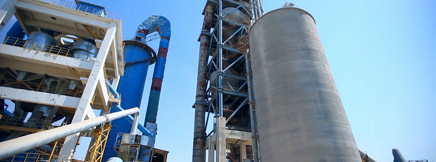
Production of cement clinker under dry method is unique in its kind, highly effective and environmentally friendly production.
Uzbek standards of clinker will be applied. The project provides for importation of raw materials to the plant (unloading) prior to transportation of clinker from the plant. In particular: technological process, technical equipment, construction, structure, electrification, automation, water supply and sewerage, heating and ventilation as well as master plan and transport scheme. The project pays special attention to dust extraction which is a main source of pollution at the cement plant; therefore, the best developments in aspiration field were applied.
Technology under dry method will provide substantial saving of fuel and energy resources and best ensures utilization of the existing plant resources of open pits and auxiliary subdivisions that will substantially raise competitiveness in domestic and international markets.
Launch of this production also created conditions for creation of additional 150 work places that plays tremendous role in employment of the population and increase of wellbeing of residents of Bekabad city.
In order to ensure optimal functioning of production line technology and quality of products as well as to save energy, this project employs the most advanced and reliable centralized separated computer system with centralized management of all shops and separated control over all shops.
This system consists of operator stations, engineer stations, site control station and systematic telecommunication network.
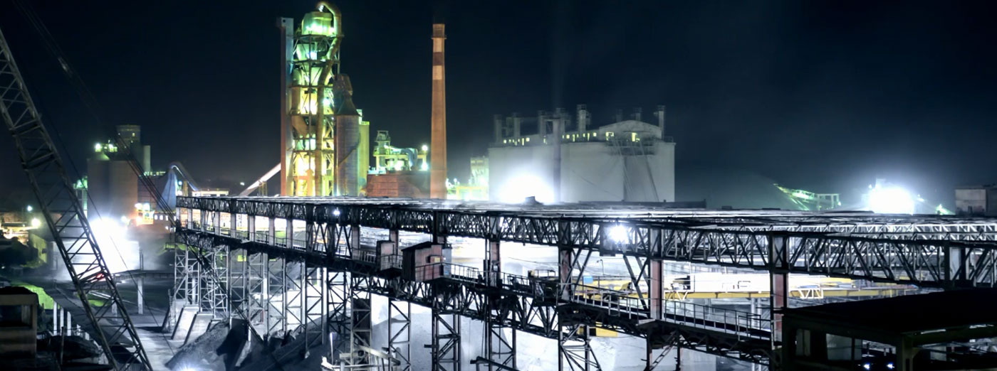
Production under wet method
Cement production process at OJSC “Bekabadcement” is carried out under wet method of clinker production and is made of main operations given in technological scheme.
1. Extraction of limestone and aeolian loamy soils.
Limestone, a main raw material component, is extracted in Jizzakh Region, “Balykli-Tau” Field at a distance of around 180 km from the enterprise. After blasting in the field, limestone is loaded by a single-bucket excavator to a motor transport and is delivered to the crushing production site located in the open pit. Limestone crushing to factions less 35mm is carried out in two stages at jaw (SMD-118 type) and hammer (SM-97А type) crushers. Crushed limestone is delivered to the cement production using railway transport.
The open pit of aeolian loamy soils is located near the enterprise at a distance of around 19 km in Syrdarya Region. Extracted loess is loaded by an excavator to motor trucks MAZ, HOVA and is transported to the enterprise and is accumulated in the warehouse (clay reserve) of the loess section.
2. Storage of raw materials and additives.
Raw material components (limestone and iron-containing additives), active mineral additives and gypseous stone after delivery to production by railway transport is separately stored in a single warehouse of the enterprise.
3. Dispensing of limestone and iron-containing additives.
At the raw material warehouse, a grab crane (G10Т40 type) with load-carrying ability of 10 tons implements dispensing of limestone and iron-containing additives to supply thereof to the main bunker of the raw material shop, and then to a reversing conveyor via a weigh hopper with a belt conveyor which is used to distribute and fill the bunkers of the raw material mill.
4. Preparation of limestone-ash sludge.
Plate feeders carry out dispensing of limestone-ash charge mixture from the raw material bunkers of mills to the mill flow; water is added parallel to the mill flow for wet grinding. The time during which raw materials pass through the mill is 20-30 minutes. Limestone–ash sludge from the mill is delivered to the sludge dip of the raw material mill and is pumped therefrom using centrifugal pumps to vertical pools Nos. 7; 8; 9.
5. Dispensing of aeolian loamy soils and preparation of aeolian loamy soil sludge.
Aeolian loamy soil (loess) is delivered to the storage bunker of the rotary mill from the clay reserve using motor transport. The material is dispensed from the storage bunker through the feeder and is delivered to the rotary mill to which water together with aeolian loamy soil is supplied for dissolution thereof and preparation of aeolian loamy soil sludge. Water for preparation of aeolian loamy soil sludge is dispensed using a valve. Then the loess sludge is delivered to the sludge dip with content 200 m3 where mixing takes place using a mixer and additional air supply. After the clay sludge is brought to the specified consistency, it is pumped by centrifugal pumps to the vertical pools No. 10; 11.
6. Storage of limestone-ash and aeolian loamy soil sludges.
After preparation, limestone-ash sludge is transported to the vertical pools No. 7; 8; 9, loess sludge is transported to the in vertical pools No. 10; 11 for separate storage and pneumatic mixing. After homogenization, sludges are sampled from the vertical pools in order to determine chemical content and other technological parameters thereof (humidity, grinding fineness, and spreadability).
7. Adjustment of sludge and preparation of normal sludge.
Adjustment of sludge is carried out in following manner: titer of grinded sludge in vertical pools is checked; then the raw material sludge is brought to the specified chemical content using the batched supply method of the loess sludge or the sludge with high titer. Further, after sludge adjustment, homogenization of the sludge is implemented by pneumatic mixing followed by sludge sampling in order to determine chemical content and other technological parameters. If the sludge content fails to conform to the specified parameters (KN, p, r), additional adjustment of sludge is implemented till the normal sludge of the specified chemical content is obtained. The normal sludge is poured into the horizontal sludge pool for storage and supply to burning.
8. Storage of normal raw material sludge.
During storage process, normal sludge in the horizontal sludge pool is subjected to mechanical and pneumatic mixing using a crane mixer in order to prevent unmixing.
9. Burning of raw material sludge.
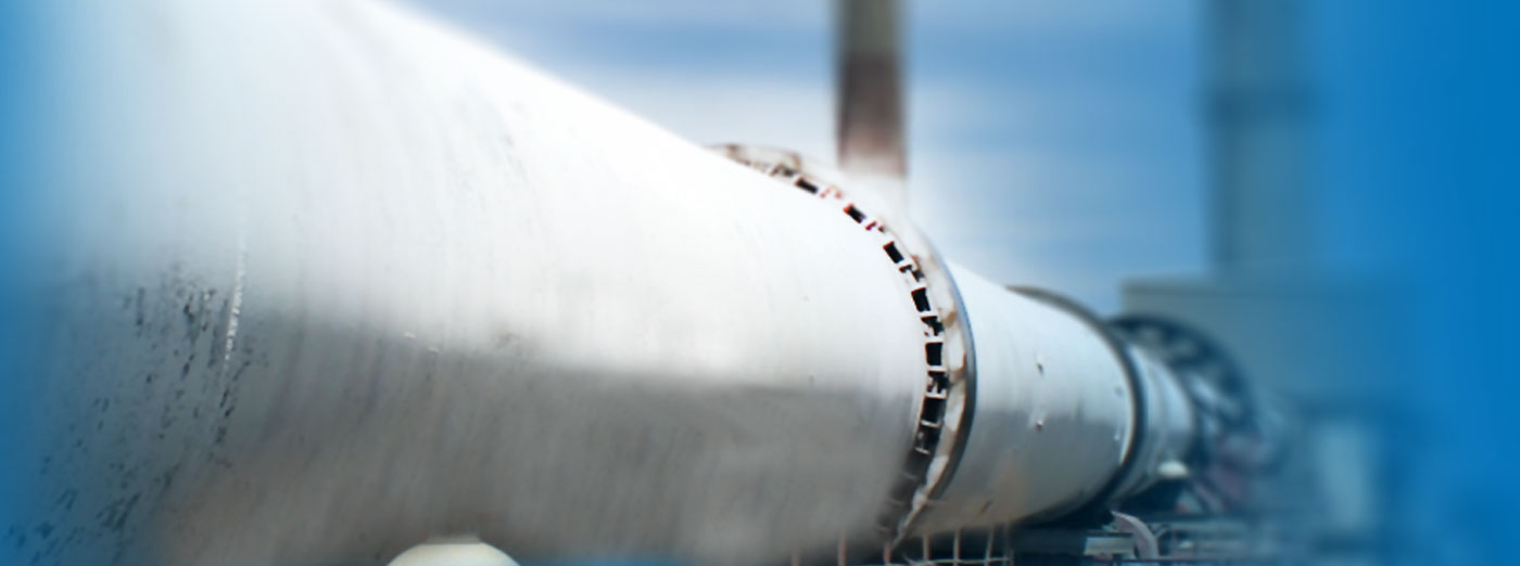
To ensure burning of the raw material mixture, at the plant there are rotary furnaces: 2 furnaces Ø4.0 х140 m with a recuperator refrigerator and 1 furnace Ø 3.6/4.0х150 m with a refrigerator “Volga 35S”.
The rotary furnaces are a counterflow burning unit in which the raw material mixture is slowly moved throughout the furnace to its hot end. The flow of hot gases moves toward the sludge. Hot gases moves due to rarefaction of the furnace which is created by a smoke exhaust.
Normal sludge is transported from the horizontal sludge pool using centrifugal GRAK pumps to the cold end of the furnace, into the sludge feeder and distribution tank where uniform distribution of sludge takes place using distribution boxes, actuating mechanisms and hoses. Through a pipeline, sludge is delivered to damping tanks and then to a control tank where control measurement of feed sludge of the furnace takes place, then sludge is delivered to the sludge mixer and the furnace through the feeder pipe.
Sludge in the furnace is subjected to high temperature. When heated, sludge is fluidized at first and then is thickened and clods are formed. Then they are disintegrated. The portion of the furnace where sludge is dried is called the zone of evaporation and drying.
The raw material mixture is further moved to the heating zone. Chemical reactions are initiated in this zone; physical properties of the raw material mixture also change. As a result of dehydration and disintegration of minerals, the clayey component loses plasticity and is scattered into powder.
The raw material mixture is delivered to the calcination zone where decomposition of chemical chalk takes place CaCO3 --- CaO + CO2. Reactions between main oxide CaO and acid oxides of the clayey component occur in this zone: SiO2, Al2O3 andFe2 O3 with formation of CaO SiO2, CaO Al2O3, CaO Fe2O3.
As the material moves further and temperature rises, the solid-phase processes of mineral generation are completed and the material will consist of calcium silicates, aluminates and ferrites. Reactions which generate these compounds are exothermal; they take place with heat emission.
Then, the material is delivered to the sintering zone where it is partially melted or sintered. The liquid phase is formed. Sintering starts at temperature of 13000С and continues at temperature up to 14500С. The material is kept in the sintering zone for 25-30 minutes. Almost the entire quick lime dissolves in the melt and participates in formation of alit during this time. (3CaOSiO2) is the main component part of clinker.
The generated clinker is delivered to the cooling zone from the sintering zone. The content of free limestone must not exceed 1% and the content of free iron must be no more than 0.35%.
Clinker is delivered from the cooling zone for quick cooling in the recuperator refrigerators at rotary furnaces No. 4 and 5, and to the refrigerator “Volga 35S” at the rotary furnace No.6, and then to the single warehouse along the clinker conveyor.
Dedusting of end gases.
Sludge burning is implemented in rotary furnaces according to the principle of counterflow of furnace gases and burnt material. End gases saturated with moisture and fine-dispersed intermediate burning products are discharged from the furnaces and are dedusted in the behind-furnace devices (a dust chamber and electrical precipitator, dust-collecting devices UG2-3-74 and DGPN-32-3SK). The coarse-dispersed portion of the behind-furnace dust is precipitated in the dust chamber. The fine-dispersed portion is entrapped by the electrical precipitator.
Sampling of behind-furnace dust
Behind-furnace dust collected in dedusting devices is accumulated in a storage bunker and is returned to the technological process.
Return of behind-furnace dust
Behind-furnace dust from the storage bunker is supplied by an elevator to a mixer and is mixed with the normal raw material sludge to supply for on burning from a cold end of the furnace. Supply of dust is also implemented from a hot end of the furnace through a dust injector using a fuller pump.
10. Storage of clinker.
After burning and cooling, clinker is transported to the single warehouse of clinker and additives for storage and further use in the technological cycle.
Active mineral additives are stored in the single warehouse as they arrive to production.
After delivery to the plant, gypseous stone is accumulated in the single warehouse of clinker and additives. If necessary, raw materials are preliminarily grinded in the hammer crusher to factions less 50mm.
11. Dispensing of clinker and additives.
The grab crane (G10 Т40 type) loads clinker, mineral additives and gypseous stone from the single warehouse to the storage bunkers of the cement mills and are dispensed to the cement mills through plate feeders. The kind of additives and mass fraction of additives and gypseous stone vary depending on the range of products.
12. Grinding of cement.
Joint grinding of clinker and additives is implemented in cement two-chamber mills (type МС) of continuous operation. Grinding fineness of the obtained cement is regulated with normative documents in respect to the range of products. The finished cement is unloaded from mills and is transported to cement silos using the pneumatic chamber pump.
13. Storage of cement.
Storage and warehousing of cement is implemented in vertical cement silos with diameter 10 m and with height 25 m, which prevent humidification and contamination of products.
Cement is stored separately depending on the range of products.
14. Shipment of cement in bulk.
Unloading devices located in the low part of silos extract cement from cement silos for shipment in bulk to special equipped railway or motor transport vehicles for delivery to consumers.
15. Packaging of cement.
Cement is transported from silos along the air tube into the packaging section. Packaging of cement in the silos section is implemented by a packaging machine into 50 kg bags as well as in 1 ton bags SSC (soft strap containers). Bags with cement are accumulated in the warehouse of a shop.
16. Shipment of packaged cement.
Cement packaged in bags is shipped from the warehouse of finished products to consumers using railway or automobile transport.